PURING AND/OR SYMMETRICAL GOLF SHAFTS
Why do shafts need puring?
Like snowflakes, no two golf shafts are exactly the
same. Every shaft contains irregularities in straightness, roundness and stiffness
that are inherent to the manufacturing process. These structural
inconsistencies can negatively or positively affect a shaft’s performance,
depending on how the shaft is aligned in the club head. Making your golf shafts
symmetrical, locates the most stable orientation in any shaft, sometimes called
the SPLINE. The process works on any golf shaft, regardless of its material;
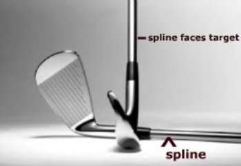
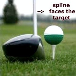
steel, or graphite. Once located, the SPLINE of the golf shaft is positioned
into the club head, so that the SPLINE is facing the target
Here is where this study of puring and making all golf shafts symmetrical gets real messed up throughout the golf industry. Much has been written about patents, where the SPLINE or NBP (natural bending position) should be placed in relation to the installation of the shaft, what should they be called, should you FLO it, what does the U.S.G.A. rule say about all this? Try researching this subject on the internet, and you are sure to be confused and frustrated. Here is our, www.golfclub-technology.com’s, KISS takes on puring, and it has worked for us for over fifteen years. The best and easiest way to explain spine aligning, puring, flo-ing, or symmetrical shafting, is our process of finding three characteristics of a shaft; the direction of maximum stiffness of the shaft, which we refer to as the SPINE, the natural and least point of resistance of a golf shaft, which we refer to as the NBP, and the plane of the shaft that when it is vibrated back and forth, its direction is on a flat line, rather than wobbling out of line, which is referred to as the FLO. Taking these three readings, we then can find what we call the SPLINE, and install it into the clubhead in the proper manner. By SPLINING your shaft, the clubface will open and close when you want it to, not when the shaft wants it to. Simple eh?
Here is how we at Golfclub-technology arrive at this plane or SPLINE:
We
use two steps to determine the optimum position to install the shaft in the
clubhead
1. SHAFT SPINNING TOOL
There are two lines we want to find using this tool.
SPINE
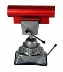
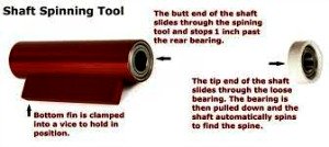
Using a bearing based, shaft spinning tool, clamped in a vice, a raw shaft is inserted into the freely-rotating bearings. A loose bearing is held about two inches from the tip, and the shaft is rotated back and forth with the tip of the fingers to find a spot where the shaft makes the most resistance. We mark this plane with our trusty sharpie. This is generally considered to be the spine, the direction of maximum stiffness of the shaft.
NBP- NATURAL BENDING POSITION
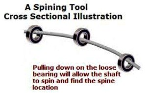
Using the same bearing based, shaft spinning tool, the raw shaft is inserted into the freely-rotating bearings. The loose bearing is held about two inches down the tip, and the shaft is pushed down with some slight pressure. The shaft willl rotate and come to rest naturally, in the direction of its least stiffness. This is its NBP (natural bending position). This is the direction the shaft wants to come to rest if lightly bent.
 |
 |
2. FLO –“Flat Line Oscillation”: Direction in which a shaft vibrates back and forth in a flat line, as opposed to wobbling out of line.
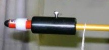
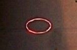
To test for FLO, we take the shaft, attach a lase pointer to the tip end, weighing the same as a driver head, and place the butt end into a frequency machine, or a very secure vise. We line up one of our marks, (THE SPINE) in the hitting direction, pull back our shaft, straight back, approximately 2 inches, and let the shaft vibrate. We are looking for a flat line oscillation, not an oval one, as illustrated below.
We repeat this procedure using the NBP mark, all the time fine tuning our marks, until we obtain the best flat-line oscillation. We can tell which FLO plane is the spine and which is the NBP by using a frequency meter. The higher of the two frequencies is the spine.
 |
 |
We then pick the best oscillation, and call it our SPLINE.
We have found, thru the years, that the spine gave the best flat line oscillation, so by assembling the club with the shaft in its most favorable orientation, in our case, with the SPLINE facing the target, off-line bending and twisting of the shaft are minimized and impact repeatability on the center of the clubface by the golfer improves up to 51%.
Try finding a golf improving tip that gives you that much improvement?
This process of club assembly, deemed in compliance with USGA standards and rules, aligns the shaft so that each club bends in the direction it should, STRAIGHT DOWN THE TARGET LINE. We hope our way of puring? has helped you understand what has become, what we feel, is one of the most facets of building a good golf club.
The major processes for manufacturing golf shafts, and see what sort of spine we can expect from each.
WELDED STEEL TUBING – Today, just about all steel shafts are made by bending sheet steel into a tubular form and welding it. The major manufacturers of steel shafts seem to have figured out how not to let the seam interfere with directional uniformity of stiffness.
Do steel shafts need puring? Definitely; Steel shafts are made by heating a flat piece of steel and wrapping it around a template called a mandrel. The ends of the steel are welded together to form what is called a weld seam. The location of this weld seam greatly affects the way the shaft performs. Straightness and roundness are also an issue in mass-produced steel golf shafts, and the puring process takes all of these factors into account.
SHEET-WRAPPED GRAPHITE - (This is also referred to as "flag-wrapped".) This approach involves taking a sheet of woven carbon fibers and wrapping it around a rod called a "mandrel". They are held together in a sheet by being impregnated with a resin. Several sheets of pre-preg, with the fibers in different directions, are wrapped onto the mandrel in multiple layers. The number of layers of each kind (and the properties of the fibers) will determine the bending and torque profile of the shaft.
Sheets that are wrapped onto the mandrel have a beginning and an end. The discontinuity at the beginning and end mean that the shaft is slightly stiffer where the extra layer is. Hence there is a potential for a spine; some directions have more fiber layers than others. In fact, sheet-wrapped graphite shafts do tend to have more spine than other types of shafts.
FILAMENT WOUND GRAPHITE - These shafts don't use a pre-preg. Instead, the individual fibers (filaments) are wound in a spiral onto a mandrel. Actually, they are more woven than wound; spirals in both directions are applied simultaneously and woven together. The process involves a pretty intricate machine to weave the fibers. After they are wound in place, they are resin-impregnated and cured. The result is generally remarkably free of spine, but we have managed to find a spine all the time. There are other disadvantages of filament-wound shafts, but consistency of directional stiffness (and consistency of specs in general) is a definite advantage.

